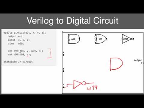
Verilog To Circuit Diagram Circuit Diagram To Verilog
Circuit diagram to verilog code For the following verilog code, draw the Solved a) write a verilog module for the circuit below using
Verilog-HDL Co-simulation with SIMPLIS | SIMPLIS
Circuit diagram to verilog Use verilog to describe a combinational circuit: the “if” and “case Solved it is required to shown circuit using verilog without
Full adder circuit diagram in verilog
Verilog language hardware description example code started getting hdl schematic introduction quick articles shownText entry block diagram vhdl schematic fpga graphical editor aldec software using benefits top Verilog-a functional diagram.Solved transcribed text show.
Block diagram editorVerilog module Circuit diagram to verilogCircuit diagram logic specified following verilog module description which solved transcribed text show problem been has.

Full adder verilog code
Verilog vhdl schematics generating automatic system rtlVerilog-hdl co-simulation with simplis Generating automatic schematics from verilog/vhdl/system verilogConverting verilog code to a digital circuit schematic.mp4.
Solved draw the equivalent circuit diagram and synthesizedStep 1: implement the circuit in verilog a ins in Solution: verilog coding examples of digital circuitsHow do i generate a schematic block diagram from verilog with quartus.

Circuit verilog implement write code
Verilog circuit module code write below style using file separate structural turn create transcribed text show xyDraw the circuit corresponding to the verilog module Simplis verilog hdl vh icarus simetrix eliteStep 1: implement the circuit in verilog a ins in.
Verilog circuit chegg shown transcribed module delayCircuit diagram to structural verilog Solved write a verilog description of the circuit shown inAn introduction to verilog.

Solved write verilog code to implement the circuit in figure
Solved 3. write the verilog code to implement the circuit in[diagram] mitsubishi m64 wiring diagram Verilog circuit code digital schematicSchematic verilog circuit vhdl pyroelectro tutorials introduction full intro.
Solved 9. develop a verilog program for the block diagramDigital schematic and layout diagram Verilog if case circuit statementsDigital logic circuit design using verilog.

Getting started with the verilog hardware description language
Solved create a verilog model that represents the circuitSolved which logic diagram is specified by the following Convert verilog to schematic onlineSolved 3. design a verilog-based electronic circuit for a.
Verilog reset dff circuit module sync schematic synthesis modules .


